Specialising in the processing of non-metallic materials
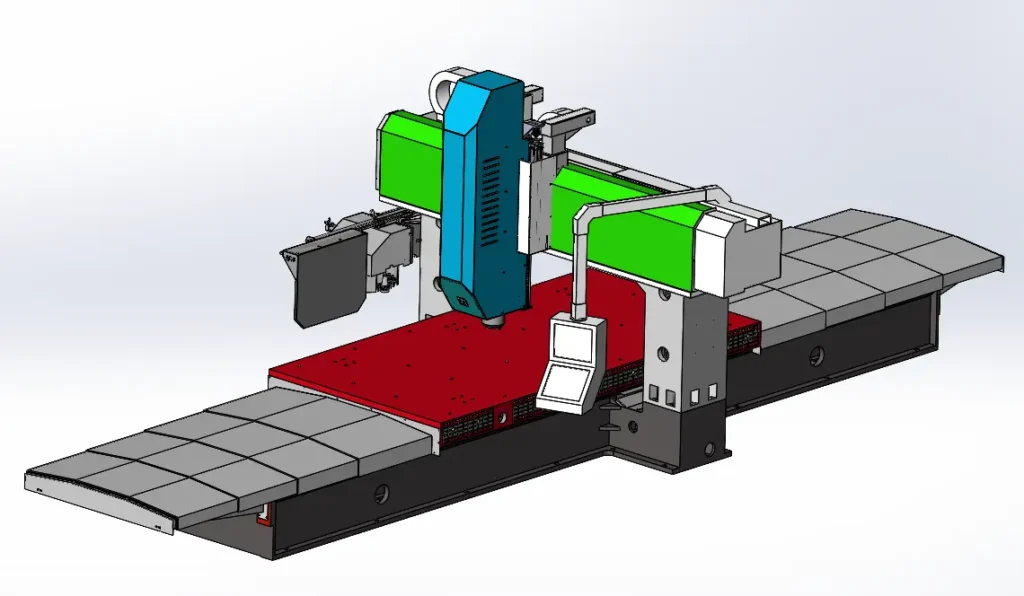
This light-duty CNC gantry milling machine is primarily designed for machining non-metallic materials.
I.Application of Light-Duty CNC Gantry Milling Machines
Light-duty CNC Gantry Milling Machines are mechanical processing equipment that integrate advanced technologies in mechanics, electronics, and hydraulics.
It is primarily used for machining flat surfaces, curved surfaces, and holes.
Light-Duty CNC Gantry Milling Machines are widely applied in the machinery manufacturing industry for roughing and finishing complex components such as plates, housings, and frames. This machine achieves three-axis interpolation: horizontal (Y-axis) and vertical (Z-axis) movements of the vertical milling head, along with longitudinal (X-axis) movement of the worktable. It supports multi-process machining, including milling, drilling, rigid tapping, reaming, and countersinking.
2. Light-Duty CNC gantry Milling machines are complete, brand-new pieces of equipment manufactured by Dezhou Tongbang Environmental Technology Co., Ltd. It features a high-rigidity structural design, reliable precision stability and retention, and comprehensive accessories. Its component design employs a high degree of modularisation and standardisation, ensuring excellent interchangeability and stable quality. The machine tool boasts advanced design, reliable performance, simple operation, and convenient maintenance. Simultaneously, Light-Duty CNC gantry Milling machines incorporate advanced European design and manufacturing technologies introduced, digested, and absorbed by our company. Its high-rigidity frame structure enables both heavy-duty cutting capabilities and precision machining of intricate components.
II. Standard Configuration of CNC Gantry Milling Machine
1. Machine Tool Gantry Frame
Light-Duty CNC gantry Milling machines’ structure comprises a bed, crossbeam, and columns forming a closed rigid frame. The worktable traverses longitudinally (X-axis) along the bed guideways. featuring a fixed, integrated ‘U’-shaped crossbeam with an exceptionally large cross-sectional area. The column and crossbeam are integrally cast, effectively preventing accuracy loss due to crossbeam sagging while avoiding verticality deviations caused by crossbeam distortion. Equipped with a vertical, high-power, multi-functional ram milling head, the milling head’s traverse table moves left and right along the crossbeam guideways, while the ram milling head performs vertical movement (Z-axis).
2. Machine Tool Base Components
The Light-Duty CNC gantry Milling machines’ overall structure comprises a bed and integral crossbeam forming a closed rigid frame. The worktable traverses longitudinally along the bed guideways (X-axis). A vertical high-power multi-functional ram milling head is mounted on the fixed crossbeam, with the milling head saddle moving laterally along the crossbeam guideways (Y-axis) and the ram milling head moving vertically (Z-axis).
3. Machine Tool Foundation Components
Key foundation components—the bed, worktable, crossbeam, traverse saddle, and ram milling head—are fabricated from high-strength cast iron using resin sand moulding. This ensures excellent vibration damping, thermal stability, and superior structural rigidity and strength throughout the machine.
4. Ram Milling Head
The vertical ram milling head employs a direct-drive ball screw mechanism powered by an AC servo motor. It incorporates an automatic tool release mechanism utilising a pneumatic-hydraulic composite release system with disc spring tensioning.
5. Pneumatic Balancing of Z-Axis Movement
Dual balancing cylinders counteract the unbalanced forces during Z-axis vertical movement. This reduces the idle torque on the ball screw, minimises wear, and maintains its precision stability. These actions are controlled by the pneumatic system.
6. Machine Guideway Configuration
The X-axis employs dual 45-degree heavy-duty linear guideways. The bed features an integral cast structure for superior rigidity.
The Y-axis utilises dual 45 heavy-duty (roller) linear guideways.
The Z-axis incorporates dual 45 heavy-duty (roller) linear guideways, enhancing both precision and rigidity.
All moving pairs operate smoothly and accurately, exhibiting wear resistance and extended service life.
7. X, Y, Z-Axis Motion Configuration
High-precision preloaded ball screws are employed for all X, Y, and Z axes.
X and Y axes feature direct connection via high-power AC servo motors, ensuring backlash-free transmission.
The Z-axis employs direct connection via an AC servo motor with a brake, ensuring backlash-free transmission.
8. Machine Tool Guideway Lubrication:
Centralised integrated self-timing quantitative lubrication systems are employed for all axis guideways. This automated system incorporates low-oil safety protection and alarm functionality.
9. Guarding and Chip Removal
The X-axis guideways are protected by steel telescopic covers. The X-axis ball screw is separately shielded by a telescopic bellows cover to prevent chip and dust contamination, thereby extending the ball screw’s service life.
The Y-axis guideways are protected by telescopic bellows covers.
X, Y, and Z axes employ drag chain protection devices.
10. Machine Tool Main Drive and Feed Drive Configuration
Light-Duty CNC gantry Milling machines’ main drive (ram milling head) utilises an AC spindle motor.
X, Y, and Z axes employ AC servo motors equipped with absolute encoders.
The Z-axis incorporates a brake-holding protection device that automatically clamps upon power loss, preventing the ram milling head’s sliding down’ or ‘runaway’ phenomena.
11. Numerical Control System
The CNC system employs Taiwan’s Neway 22MA, with system functions and configuration adhering to the manufacturer’s standard specifications.
12. Electrical Control Auxiliary Devices:
Fully enclosed electrical cabinet with standard protection and sealed dustproofing.
The main operator console facilitates convenient operation and control, equipped with an electronic handwheel. The machine incorporates automatic overload protection and an alarm for the servo system, alongside mechanical power failure protection.
Software limits are set for all machine movement axes.
Equipped with a vacuum pressure sensor. Should vacuum pressure fail to reach the set value, the CNC system will trigger an alarm and automatically halt machining.
13. Machine Tool Operating Environment
Power Supply: Three-phase AC voltage 380V ±10%, frequency 50Hz ±1%.
Ambient Temperature: 5–40°C.
Relative Humidity: ≤85%.
III. Principal Technical Parameters of the light-duty CNC gantry milling machine
1. Workbench Specifications
Workbench Dimensions (Width × Length) 1600 × 2500 mm
Distance Between Two Columns 1730 mm
Table Load Capacity 3000kg
2. Feed Axis Movement Parameters
X-Axis Travel: 2700mm
Y-Axis Travel: 1800mm
Z-axis travel: 500mm
X, Y, Z-axis feed rate (stepless) 1-8000mm/min
X, Y, Z-axis rapid traverse X, Y, Z-axis 10000mm/min
3. Spindle Parameters
Distance from vertical milling head spindle face to worktable: 120-620mm
Vertical milling head spindle motor power: 7.5kW
Maximum spindle speed: 10000 (rpm)
Tool holder type: BT40
4. Other Specifications
Overall machine dimensions (L×W×H): 7000×3600×3200mm
Machine weight (approx.): 10 tons
Total electrical power consumption (approx.): 17kW
IV. Principal Structural Features of the Machine Tool
1. Gantry Frame
Foundational components, including the bed, worktable, integrated crossbeam, traverse saddle, and milling head ram, are cast from high-strength, premium-grade cast iron using resin sand moulding. These undergo dual treatment of artificial ageing and vibration ageing. The rational structural design ensures excellent castability and machinability, delivering high rigidity, superior deflection resistance, and outstanding precision stability.
The gantry frame comprises an integrated crossbeam and bed, with the lower end of the crossbeam rigidly connected to the bed to form a highly rigid gantry structure.
Our advanced machining equipment and processes ensure excellent overall machine accuracy and long-term stability, providing a reliable guarantee for extended machine tool service life.
2. Bed and Work Table
The bed serves as the machine tool’s foundational component, possessing sufficient rigidity and a rationally designed cast structure. The worktable functions as a dedicated vacuum-assisted platform, facilitating the machining of thin-plate workpieces. The machine bed features an integral cast structure with excellent structural rigidity. The worktable guideways employ heavy-duty linear guides, endowing the worktable with high load-bearing capacity, responsive motion, smooth low-speed movement without crawling, and superior vibration damping.
A ball screw is positioned between the bed and worktable guideways, employing a dual-nut preload structure. The drive and tail ends of the screw are supported by NSK specialised bearings, with the tail end incorporating a pre-tensioned screw mechanism. These features enhance transmission rigidity while compensating for thermal deformation errors. Both support brackets for the screw are fixed to the bed, while the nut housing resides on the worktable.
3. Crossbeam and Cross Table
The crossbeam constitutes a critical component of the gantry machine tool. Beyond supporting the vertical milling head, it bears the primary cutting forces generated during machining operations. It must possess sufficient rigidity to ensure machining accuracy. The beam adopts a closed box-type structure. Its internal layout incorporates strategically positioned stiffeners, significantly enhancing the beam’s torsional rigidity. This design allows for increased support spans, enabling the vertical milling head’s transverse slide to be securely positioned and operated on the beam. Consequently, the transverse slide’s motion rigidity is greatly enhanced, allowing the vertical milling head to withstand heavy cutting loads.
The front guideway of the traverse saddle serves as the vertical guideway for the ram milling head. A double-nut preload structure ball screw is mounted on the traverse saddle. Both the drive and tail ends of the screw are supported by specialised bearings. The tail end incorporates a pre-tensioning mechanism to enhance transmission rigidity while compensating for thermal deformation errors. The two support bases for the ball screw are fixed to the traverse saddle, while the nut base is secured to the ram milling head.
We also offer customisation services. We can tailor gantry milling machines to the material and dimensions of your workpieces. Please contact us for details.