
CNC gantry milling machine is a commonly used large-scale machining tool. Primarily employed for processing flat surfaces, inclined planes, spatial curved surfaces, and special-shaped parts on large workpieces, it excels in batch production thanks to its high precision and efficiency.
While its structure may appear complex at first glance, breaking it down reveals a clear framework. Below, we explain its core components in plain language to help you quickly grasp the equipment’s fundamentals.
I.The Bed of CNC Gantry Milling Machine
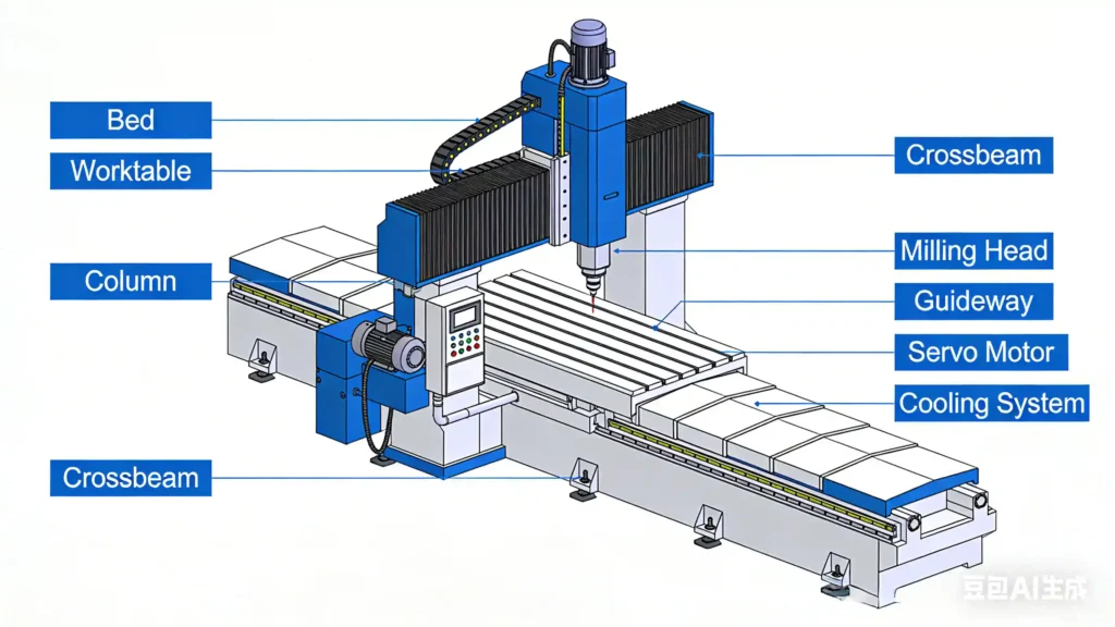
First is the bed (Bed), serving as the “foundation” of the CNC gantry milling machine and providing the fundamental structural support for the entire device.
Most beds are constructed from high-strength cast iron, which undergoes aging treatment to eliminate internal stresses. This process effectively ensures rigidity and stability, preventing vibrations during machining that could compromise accuracy. The X-axis guide rail is mounted on the bed, with the worktable resting upon it. The bed surface is typically covered with a protective cover to shield the guide rail from damage by iron chips and oil stains.
II.The Frame of the CNC Gantry Milling Machine
Next is the machine’s “skeleton”—the gantry frame, composed of columns, crossbeams, and top beams.
Its name derives from its resemblance to a traditional Chinese archway [3]. Symmetrically mounted on both sides of the bed, the columns, top beams, and crossbeams form a robust portal structure whose rigidity directly determines machining precision [2]. The crossbeam can move vertically along the column guide rails to adjust machining height. On some models, the crossbeam also allows for horizontal fine adjustment to accommodate workpieces of varying dimensions [5].
III.The Head of the CNC Gantry Milling Machine
The core machining unit mounted on the crossbeam is the milling head, serving as the machine’s “cutting tool” and the key component for performing machining operations.
Common types include the Vertical Milling Head, Horizontal Milling Head, Universal Milling Head, and Boring and Milling Head: The Vertical Milling Head spindle is perpendicular to the worktable, suitable for milling flat surfaces and steps; Horizontal milling heads feature a spindle parallel to the worktable, enabling groove and bevel machining; Universal milling heads can adjust the spindle direction for multi-angle machining; Boring and milling heads combine boring and milling capabilities, suitable for complex parts. Each milling head features an independent motor, speed change mechanism, and spindle assembly, with maximum power reaching 150 kilowatts (150kW), meeting diverse cutting requirements.
IV.The Worktable of the CNC Gantry Milling Machine
The workpiece is clamped onto the worktable and mounted on the bed guideways, enabling longitudinal feed movement (X-axis movement) along the guideways. The worktable surface features T-slots, facilitating workpiece clamping with pressure plates and screws to prevent shifting during machining [3]. Its dimensions and load capacity determine the size of workpieces the machine can process; large gantry milling machines can have worktables several meters long with load capacities exceeding 100 tons.
V. The feed system of the CNC Gantry Milling Machine
Precise movement of all components is driven by the feed system, comprising servo motors, ball screws, and guideways. Servo motors receive commands from the CNC system, converting rotational motion into linear motion via ball screws to drive the movement of components like the worktable, crossbeam, and milling head. Specifically, the worktable’s longitudinal movement constitutes the X-axis, the milling head’s lateral movement along the crossbeam forms the Y-axis, and the vertical lifting of the milling head defines the Z-axis. Three-axis interpolation enables complex trajectory machining. Guide rails ensure smooth and precise motion, with roller linear guide rails being commonly used for enhanced rigidity.
VI.The CNC system of the CNC Gantry Milling Machine
The CNC system serves as the “brain” of the entire machine, controlling all component operations.
Operators input machining parameters—such as spindle speed, feed rate, and cutting depth—through programming. The CNC system processes these commands and coordinates the synchronized operation of all components. Leading systems include Siemens, Fanuc, and Huazhong CNC, featuring intelligent functions like tool wear monitoring and machining error compensation. These systems enable both automated machining and manual operation adjustments.
VII.The Auxiliary systems
Additionally, auxiliary systems like lubrication and cooling systems are integral components.
The lubrication system reduces component wear and extends equipment service life through continuous oil supply.
The cooling system lowers temperatures during cutting to prevent tool overheating and damage to the workpiece.
Though these auxiliary systems do not directly participate in cutting, they ensure stable equipment operation, and beginners should understand their functions.
The above outlines the core structure of a CNC gantry milling machine. Only through the coordinated operation of all components can high-efficiency and high-precision machining be achieved. For beginners, first grasping the functions and operational logic of each component will make subsequent operation and maintenance much smoother. Familiarity with these fundamental structures is also a crucial step toward becoming a qualified machining operator.
- 5 Core Factors of CNC Gantry Mill Bed Structure and Long-Term Precision Stability
- CNC Gantry Machine Delivery Time, Installation & Overseas Commissioning: 5 Real Steps from the Field
- Which is better, a moving table or a moving column gantry machine?
- 5 Practical Guides: Fixed Beam CNC Gantry Machine – Features, Advantages & Suitable Processing Scenarios
- How to Choose a CNC Gantry Mill for Plastic, Acrylic, PVC & PE Machining?